The 3-D scanner I am building will use a Raspberry Pi running Freelss open source software. I am currently installing all the dependencies and the other pieces of small software such as Raspicam etc, in preparation for installing the Freelss software itself.
When running the 3-D scanner will connect wirelessly to a laptop over the local wi-Fi network and be controlled from the laptop and the 3-D models can then be saved.
I will Post about the next stage in the 3-D scanner build next week.
3D Prints Collection

Friday, 18 December 2015
Monday, 14 December 2015

Monday, 7 December 2015
3D Scanner Assembly
I have started assembling the 3-D Scanner, with help from my younger brother, as it turned out to be a four hand job.
 |
| The 3-D Printed parts were assembled using machine screws and nuts |
 |
| The fully assembled turntable arm. The stepper motor can be seen at the top with its cables running down the arm to where the camera tower will be attached. |
Monday, 30 November 2015
3-D Printer Repair - Fractured X Axis Belt Tensioner - Fitting The Part
The 3-D printed part required no post printing finishing, such as filing or drilling, so could be fitted as soon as the 3-D Printer had cooled down.
The fitting process required disassembling the central Print Head Bracket on which both plastic extruders and the three fans are fitted, but the replacement fitted correctly.
The fitting process required disassembling the central Print Head Bracket on which both plastic extruders and the three fans are fitted, but the replacement fitted correctly.
 |
| The fitted part. |
Protobox CNC machine.
I am hopeful to expand my prototyping and modelling capabilities and would love to own a Probotix CNC machine. I think they really look good you can see them on this link: http://www.probotix.com/
If I recover from Inflamatory Arthritis (and stop being an improverished student) I would certainly buy one of these CNC routers.
Thursday, 26 November 2015
3-D Printer Repair - Fractured X Axis Belt Tensioner
My 3-D printer is a Rep-Rap style machine and therefore it is made from several 3-D printed plastic parts. Recently one of these components broke. The part which holds the X axes stepper motor belt fractured as you can see in image.
 |
| Broken belt tensioner for the X axis. |
 |
| The 3-D Printed replacement component. |
This demonstrates the benefit of the Rep-Rap 3-D printer model as it allows components which are under stress or wear to be manufactured by the 3-D printer itself, reducing the need for components manufactured elsewhere to be stocked.
Wednesday, 25 November 2015
The 3-D Scanner Electrical Components have arrived!
The electrical components for the 3-D scanner have now arrived:

They include two specially manufactured lasers (which are directed at the object being scanned to provide reference points to calculate the scale), an additional circuit board to work with the Raspberry Pi, a stepper motor and all the required nuts and screws to assemble. Shortly I will be able to begin the assembly of th scanner using the plastic parts I have 3-D printed.

They include two specially manufactured lasers (which are directed at the object being scanned to provide reference points to calculate the scale), an additional circuit board to work with the Raspberry Pi, a stepper motor and all the required nuts and screws to assemble. Shortly I will be able to begin the assembly of th scanner using the plastic parts I have 3-D printed.
Tuesday, 17 November 2015
Extruder Tolerance - Preventing Blocking the Extruder - Working withCheaper materials
I have been experimenting with the tolerance of the input filament diameter. Which becomes and issue when working with filaments which have variable diameters along their length, usually cheaper materials. My printer uses a input filament diameter of 1.75 mm and I have found that above a tolerance of 0.01 mm causes the printer head to block up, due to too much material being forced through the printer nozzle (A printer head block up is a slow and laborious task to clean out, and if it occurs during print the model is ruined).
I have found that cheaper materials, bought online, usually have sufficiently good material properties, but have a less accurate diameter, which often varies through the material.
To overcome this issue, I recommend taking a series of precise measurements using a micrometer along the length of filament you expect to use in a particular print. Find the average diameter and then input this value into the G code generating software so that the rate of material input can by modified.

In Cura software change this value:
(In the basic settings)
 In Sli3r software you have to go into the filament settings and change it:
 This is an additional process which is required only with lower quality filaments, but means a lot of money can be saved especially when printing large volumes. Lower cost filaments bought directly from China can be up to five times cheaper then branded materials from large companies such as Makerbot and Cubify.
I have found that cheaper materials, bought online, usually have sufficiently good material properties, but have a less accurate diameter, which often varies through the material.
To overcome this issue, I recommend taking a series of precise measurements using a micrometer along the length of filament you expect to use in a particular print. Find the average diameter and then input this value into the G code generating software so that the rate of material input can by modified.
In Cura software change this value:
(In the basic settings)

 This is an additional process which is required only with lower quality filaments, but means a lot of money can be saved especially when printing large volumes. Lower cost filaments bought directly from China can be up to five times cheaper then branded materials from large companies such as Makerbot and Cubify.
Tuesday, 10 November 2015
3D Scanner.
Through a Kickstarter campaign called Atlas 3-D scanner (https://www.kickstarter.com/projects/1545315380/atlas-3d-the-3d-scanner-you-print-and-build-yourse) I have started a project to build my own DIY Open source software 3-D scanner.
Called 'ATLAS 3D - The 3D Scanner You Print and Build Yourself!', the scanner uses a Raspberry Pi as the processing unit with all the plastic components 3-D printed.
The first thing I have completed is to 3-D print all the components for the scanner.
Here are some images:

Called 'ATLAS 3D - The 3D Scanner You Print and Build Yourself!', the scanner uses a Raspberry Pi as the processing unit with all the plastic components 3-D printed.
The first thing I have completed is to 3-D print all the components for the scanner.
Here are some images:

Friday, 6 November 2015
3D Printed Model Jet Engine
I completed this small project ages ago but didn't get round to posting about it. Here is an image of the model of a GE aviation jet engine I made using the designs from thingiverse. I used it as an opportunity to refine the printing quality and practice the print start up procedure.

Wednesday, 4 November 2015
Long time no blogging.
I am sorry I have not been adding any posts to my 3-D printing blog recently, I have been busy building and launching a website and online show room for a local motorcycle repair service and sales company.
I will be getting back to my 3-D printing projects and have many aspects to write about.
I am now going to try to release at least one post per week, every week for the next year, until I go to University next October.
Friday, 7 August 2015
Slic3r
Now that I am having consistent high quality prints I've decided to start working with different more complex Slic3r software to further improve the quality and reduce print time. I am also using additional features such as printing multiple components continuously in one G-code program, especially useful for producing large numbers of small components.
 |
| Multiple copies of a component for the Open source 3D Scanner project I am currently working on. This feature speeds up the manufacturing process as less human inout is required. |
Wednesday, 15 July 2015
Temperature
I stared printing with some different PLA filament today, and the print quality was terrible. The materials was not flowing well, jamming in the head causing thinning and breaking of the walls. At first I through that there was moisture in the filament as it was making a crackling sound when printing. However, increasing the temperature in attempt to drive out any water made the situation worst. After experimenting with a range of temperatures, reducing the temperature to 200° solved the problem.

Although you would think increasing the temperature would make the plastic less viscous and therefore flow better, in some cases increasing the temperature can cause the plastic to start to depolymerise, causing it to thicken and jam the Print Head.
Tuesday, 14 July 2015
Further Calibration
I have printed a extremely detailed and complex test piece to highlight the weaknesses of my 3-D printer so I can improve the precision and quality of its prints.

I will work on the settings and setup of the printer to improve the overall quality, and then reprint this test.
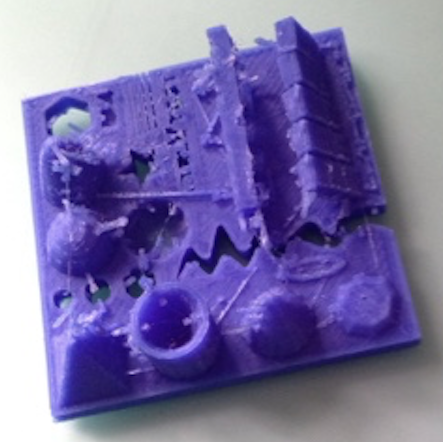
The model included a range of slopes at angles between 20° and 45°, cones, domes zigzag shapes and precise holes. My printer performed very well on all the tests except for moving between the pointed object where it left strands of material. This is due to it insufficient retraction of the filament to empty the nozzle, so as the Print Head moves over a empty space is dribble plastic. I will now experiment with different levels of retraction to find an optimal value to minimise oozing from the nozzle when its travelling between print areas.
I will work on the settings and setup of the printer to improve the overall quality, and then reprint this test.
Saturday, 4 July 2015
Z Axis Stepper Motor Clutch Tool
When starting a new print, it is often required to manually alter the Z axis level to achieve very good adhesion achieved by rotating the clutch on the stepper motor. The clutch is very stiff, and difficult to move as there is little to grip onto. I have additional difficulty due to Arthtitis in my wrists, therefore I decided to produce a tool to make the process easier.
This really demonstrates the power of 3-D printing for rapid prototyping as the design and manufacture of the tool was completed in around one and a half hours. I quickly designed the shape using Google Sketchup software, generated the tool paths using Cura software and printed it using PLA material.
 |
| Using the Tool to rotate the Z Axis clutch |
 |
| I included a X shaped centre to reduce the quantity of material required and the print duration. |
Tuesday, 30 June 2015
Fine Calibration.
When I first started 3-D printing I found the calibration process difficult as there were few online resources or information about this critical process. I have now built quite a reasonable experience of 3-D printing after working with my machine for 18 months, and have improved my calibration technique. I will discuss the calibration now to add another online resource for newcomers to 3-D printing.
There are three elements which are critical to the fused deposition modelling (FDM) process, bed levelling, first layer height and plastic flow rate, underperformance in any one of these can cause total failure of the printed model.
Bed Levelling:
Most 3-D printers on the market currently use a three point bed levelling system, where the adjustment of three nuts changes the height of the bed in relation to the Printer Heads. It is imperative that the printheads move parallel to the bed in both the X and Y axes. So that the space between the extrusion nozzle and the bed is constant. If this distance changes the amount of adhesion between the printed model and the bed varies, causing the model to lift from the bed and/or distort. Some 3-D printers are starting to appear which have automatic bed levelling removing this time consuming process.
The tried and tested technique is to slide a business card between the nozzle and the bed and then, with the mains power disconnected, manually move the printhead across the X axis. Rather then see the gap between the printhead and the bed you feel it with the business card, if the card becomes tight then the bed needs to be dropped by tightening the nuts on the underside. This process is then repeated in the Y axis direction. It is worthwhile repeating this process many times and devoting a large amount of time as a unlevelled bed can prevent sticking of the first layer and cause unsuccessful printing.
First Layer Heigth:
For good adhesion of the printed model it is best advised to have a thicker first layer to aid adhesion, but this layer should be compressed to help it bind to the bed, especially important when printing on blue tape which relies on the physical bond between the tape rather then heat. The height of the first layer can be controlled in the slicing software, software which converts 3-D model into layers and generates commands for the printer to follow, both Cura and Slic3r allow variable inputs. A value of between 0.15mm to 0.2mm has good results. To compress the first layer you manually move the position of the Z axes home. This varies from printer to printer but usually involves an adjustable component which breaks a light to gate telling the printer it is at zero for that axis. So the position the printer thinks is zero on the Z axis is actually minus 0.1mm, for example, so when the printer is making a line which is 0.2mm thick, it is actually 0.1mm and is being compressed onto the bed, providing a solid foundation for a long print and reduce the risk of the print model curling and lifting.
Plastic Flow Rate:
The plastic flow rate effects the wall thickness of the printed models, and is affected by the material feed stepper motors rotational speed, the filament thickness and the nozzle diameter. It is important that the exact diameter of the nozzle is known as this value is used by the slicing software to calculate the number of lines required for a specified wall thickness.
If the flow rate is too low and then the walls thin and can break causing a failed print. The most common cause of this problem is the filament jamming in the printhead, due to the printhead not being at, or slightly above, the glass point temperature (The temperature at which the material starts to become a liquid and flow, the higher the temperature above this point the less viscous the liquid) of the printing material or that the feed stepper motor is forcing too much material into the head causing it to jam. Both issues I have experienced.
Temperature is easily fixed when using Printrun software to control the 3-D printer as it can be manually changed. When working with a new batch of material I manually push some filament through the Print Head, varying the temperature and testing the resistance to find a suitable temperature for good quality printing, as each batch of plastic can vary.
If the material feed stepper motor is forcing too much plastic into the head this is usually due to the diameter of the nozzle diemention being inaccurate, and the Slicing software calculating the flow rate to be greater than it is, so the material enters the head at a greater rate than it can exit, thus causing jamming. This highlights the importance of an accurate measurement of the nozzle diameter.
The flow rate also affects the precision of the printed models, if too much plastic is being extruded then the wall thicknesses will be greater than designed thus the model's dimensions will be larger than expected and this can affect the assembly of multiple components.
Friday, 26 June 2015
Getting the Printer up and running again.
I have now got the 3-D printer up and running again and will discuss some of the maintenance I carried out on it.
Firstly I attended to the wiring, checking all the connectors on the central processing unit and in some cases reworking the connections to prevent errors such as oscillating stepper motors which the machine has suffered from. The thermostats on the printheads then needed reglueing in the correct position, with high temperature glue, so after calibration, they now read the temperature of the Hotends very accurately.
I then brought each print head up to operating temperature, 200° C, to clean the inner channels from the buildup of plastic and any carbon residue. The primary printhead which has become blocked with carbonised denatured nylon is proving very difficult to clean out and will require the full disassembly of the head, in the meantime I am going to use the secondary head to print with. This is not an easy change over and I will have a blog entry explaining how I achieve this.
Finally I then checked all the moving components were well lubricated, tightened the belts which control the X and Y movement and tightened the Allan screws to prevent any vibration during operation.
I then moved to fine calibration.
Tuesday, 23 June 2015
Projects.
I have several projects that I am looking forward to getting my teeth into and getting the 3-D printer up and running again. Firstly I've got a lot of work to do on the printer maintenance wise, during the technology projects I jammed up the primary printer head with nylon which I think has denatured and carbonising formed a solid block inside the head. After cleaning that out, some of the wiring around the printheads has become loose which needs attention to have reliable printing. Then I'm going to work on maximising the precision of the 3-D printer aiming for 40 µm resolution and 0.05 mm layer thickness, using a series of complex test prints with peculiar curved shapes and high detail to really push the performance of the printer. To give a comparison the Makerbot replicator, a commercial product, has a precision of 100 µm, which I am aiming to surpass.
I have another few smaller projects I didn't quite finish over Christmas which I'm going to work on before starting some big projects which I've been looking forward to for a long time.
The first project is to enter some of the Makerbot STEAM (Science, Technology, Engineering, Art and Maths) challenges. You can check them out here: http://www.thingiverse.com/challenges/ I will have future blog posts showing my entries.
The next project is to build a 3-D scanner. I backed a 3-D scanning project on Kickstarter called Atlas 3-D. It was successfully funded in February and I am looking forward to the delivery of the electrical components sometime in July to build the scanner. The parts include the stepper motor, wiring and lasers and then I will use a Rasberry Pi and Rasberry Pi camera and print of the other components to assemble a DIY style Open source 3-D scanner. The 3-D scanner will run on Open source software, which I have been following the development of, called FreeLSS. (https://github.com/hairu/freelss)
I then will be designing and 3-D printing a range of small models of classic commercial vehicles, in 1/50 scale. I have collected vintage vehicle models for some years and I am going to develop my own models of vehicles and trailers which are not available as commercial models.
So it's going to be a busy summer holidays.
Monday, 22 June 2015
Long time no printing.
I have been somewhat plagued with ill-health and exams so have been unable to carry out any 3-D printing related projects. Struggling with arthritis it is going to be very difficult for me to work on all the projects I planned to complete this summer however I will fight on. Typing is very difficult however I am now making use of the dictating feature on the iPad so I can still complete my blog posts. I have completed my A-level technology project and will write a post about it and then have a series of projects I am looking forward to working on over the coming months.
Friday, 23 January 2015
Oscillating Material Feed Stepper Motor
My 3D Printer has suffered from Oscillating Stepper Motor which although rare seems to have occurred to other RepRap style Printers; when the stepper motor which feeds the material into the Print Head repeatedly changes direction, causing no overall movement of material, and preventing printing. At first, I thought this could be a loose connection in the mother board and general circuitry of the 3D Printer, but after checking all the wiring and connectors, this was eliminated. I then though it was a software issue, sending a corrupted signal. However, after great research I am still unsure about the root of the problem. One option, which I was reluctant to follow, was to reformat the 3D Printers software. Another idea, because my Printer is a dual extrusion model, with two Print Heads, thus two feed motors, was to swap the connections, so that the second motor would take the first motors command and feed into the fist extruder. Although a short term fix, it worked; so the problem isn't software related but must be in the stepper motor, or its wiring. Before progressing any further I will contact the manufacture, to enquire, and potentially get a replacement stepper motor, to solve the issue. Up un to now, I have had very little hassle with the general running of the 3D Printer and it has enabled me to develop my CAD/CAM skills, especially in design preparation for additive layer manufacture.
I have experienced this problem again today (02/07/2015), this time both stepper motors oscillating instead of rotating when sending the manual command to extrude 5mm of plastic. I fixed the problem by removing the stepper motor connections from the circuit board of the printer and then reconnecting them, checking for any loose connections.
I have experienced this problem again today (02/07/2015), this time both stepper motors oscillating instead of rotating when sending the manual command to extrude 5mm of plastic. I fixed the problem by removing the stepper motor connections from the circuit board of the printer and then reconnecting them, checking for any loose connections.
Friday, 9 January 2015
3D Printer Hotend fix.
I experienced quite a catastrophic printer failure today, when the temperature of the Hotend (the component which the plastic filament passes to become molten before extrusion) raised rapidly to 250°+ causing the carbonisation of the PLA material. After quickly shutting the printer down, and increasing ventilation to clear the burnt plastic smell I investigated the cause of the failure. The thermostat had disconnected from the main heatsink of the Hotend, which meant that it was heavily under-reading.
After some research, and much thought, I worked out a process to reaffix the thermostat to the hotness. Simply glueing the thermostat back onto the Hotend, could potentially effect the sensitivity of device, and was the original fixing method. (Which evidently failed) Therefore, I decided to use wire to tie the thermostat to the Hotend positioning it onto the heatsink, providing maximum temperature accuracy. Only a small job, but without accurate temperature control, successful prating is almost impossible. I considered the effects of heat conduction though the wire tie, but decided that this would be insignificant and would not cause any harm to the cables as they all have heat resistant outer covering.
I attach two images of the Hotend in my printer, with the wire fixing holding the thermostat in place.
 |
| Disassembly of the PrintHead, notice the thermostat and circuitry (on LH Hotend) disconnected from the Hotend. |
 |
| The insulated cabling tied to the Hotend, holding the thermostat onto the Heatsink for optimal reading accuracy |
Subscribe to:
Comments (Atom)